Abstract
Internal winding short circuit is one of the most destructive hidden faults in power transformers. This article uses a real 500kV autotransformer fault as an example to explain how electromagnetic field modeling and system circuit modeling can be combined to invert and locate internal short-circuit points from fault recording data — avoiding blind tank lifting and core pulling, thereby reducing outage time and major overhaul costs.
1. Common Pain Points for Asset Owners and O&M Teams
When managing large power transformers in substation and distribution network projects, asset owners and operation teams often face the following challenges:
- Traditional protection relays can only trip the unit, but they cannot accurately locate the fault position inside the winding.
- Relying solely on offline dissolved gas analysis (DGA) of transformer oil leads to long diagnostic cycles and may miss the best maintenance window — especially for high-voltage units where outage penalties are severe.
- Blind tank lifting and core pulling for full internal inspection involve high labor costs and long outage times, and re-energizing a defective unit is strictly prohibited per safety regulations.
2. Real 500kV Transformer Fault Case
In early 2025, a 500kV autotransformer suffered an internal winding short-circuit fault. The protection sequence unfolded as follows:
- Buchholz relay and pressure relief protection operated first.
- Differential protection tripped after approximately 22 ms.
- DGA characteristic gases indicated internal arc discharge.
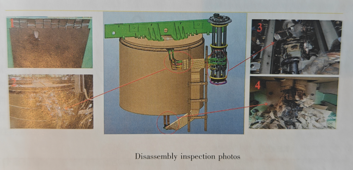
- On-site disassembly inspection found severe burn damage on the tap-winding outgoing insulation, broken conductors, and obvious arcing traces on tap-changer contacts.
Table 1: Fault Oscillogram Characteristics
Table 1: Fault oscillogram characteristics. The fault evolves from inter-turn short circuit to ground short circuit.
| Electrical Quantity | Phase I | Phase II |
|---|---|---|
| HV C-phase voltage | Zero-sequence current and differential current appear | Zero-sequence current and differential current gradually increase |
| HV zero-sequence current | Begins to appear | Gradually increases |
| MV C-phase current | C-phase current begins to increase | Sudden surge in current |
| MV C-phase zero-sequence current | Starts to rise | Continues to increase |
| MV C-phase voltage | Voltage begins to fluctuate, slightly decreases | Voltage drops significantly |
| C-phase common winding current | Distortion appears | Fault current component increases |
| C-phase common winding zero-sequence current | Starts to rise | Becomes more prominent |
Table 2: Short-Circuit Fault Current Analysis
Table 2: Short-circuit fault current analysis. T₁ is normal operation; T₂ and T₃ are fault instants. The MV winding current rises sharply during the fault.
| Time | HV Winding / A | MV Winding / A | LV Winding / A |
|---|---|---|---|
| T₁ (Normal operation) | 573.2 | -1443.8 | 876.1 |
| T₂ | 707.8 | 7677.2 | -8307.1 |
| T₃ | 4188.1 | 62580.4 | 4579.5 |
To put this in perspective: using the conventional workflow would require tank lifting → core pulling → full visual inspection — a process that takes several days and keeps the corresponding bus section out of service, resulting in significant economic loss.
3. Optimized Diagnostic Approach: Field-Circuit Collaborative Inversion
In contrast to pure algorithm diagnosis or single-circuit simulation, this case adopts a field-circuit collaborative modeling method: the transformer electromagnetic field model and system circuit model are bidirectionally coupled, and fault recording data is used to invert the location and severity of the internal winding short circuit.
Table 3: Fault Diagnosis and Location Flowchart
Table 3: Fault diagnosis and location flowchart. The workflow iteratively optimizes the inversion algorithm until the results match the fault recording data.
| Step | Action | Output / Next Step |
|---|---|---|
| 1 | Start | Initiate field-circuit collaborative modeling |
| 2 | Build electromagnetic field model | Achieve field-circuit bidirectional coupling |
| 3 | Build system circuit model | |
| 4 | Establish inversion mathematical model | Define the relationship between fault location and electrical response |
| 5 | Solve the model | Obtain preliminary fault location result |
| 6 | Verify inversion results with fault oscillogram | Decision: Are results accurate? |
| 7a | If No — Optimize inversion algorithm | Return to Step 4 |
| 7b | If Yes — Engineering application | Apply result to maintenance decision |
| 8 | End | Fault location confirmed |
Most importantly, actual performance of this method delivered:
- Maximum fault-location error below 3.2% — validated across 11 simulated short-circuit locations.
- No need to lift the tank cover in the early diagnosis phase.
- Capability to identify inter-turn short circuit, phase-to-earth short circuit, and inter-winding short circuit.
- Fault evolution trend simulation before maintenance, guiding precise overhaul planning.
4. Disassembly Inspection Verification
Factory disassembly inspection confirmed the inversion results: the upper outgoing line insulation of the regulating winding was damaged and extensively fractured — the suspected discharge initiation area — while the oil tank shielding insulation cardboard had perforations marking the discharge landing points. Fig. 1 shows the on-site disassembly inspection photos and fault location schematic.
5. Business Value
- Reduced outage time: Lock the fault zone before disassembly so maintenance is targeted and controllable.
- Lower overhaul cost: Avoid repeated tank lifting and core pulling — each iteration can cost tens of thousands of dollars in labor and lost revenue.
- Improved O&M safety: Prevent mistakenly re-energizing a defective transformer.
- Long-term asset health: Provide technical references for preventive maintenance, protection scheme optimization, and next-generation transformer design.
Ultimately, internal short-circuit faults in power transformers are highly concealed and costly. Reliable fault diagnosis capability helps you control outage risks in advance and avoid major economic losses.
Technical Consultation
If you are working on substation, distribution network upgrade, or transformer asset management projects and need technical support for transformer fault diagnosis and risk mitigation, please share your project information. We can assist you with:
- Tailored technical recommendations for substation transformer asset management.
- Full case documentation and fault analysis checklists.
- Reference materials related to transformer maintenance and DGA assessment.
- Reference documents for bidding purposes in compliance with relevant standards.
Prefer a product catalog? Explore our oil-immersed transformer series (10 kV, 30–2500 kVA) designed with low-loss core design and IEC-compliant insulation.