Many people new to power systems ask: once a transformer is commissioned, can it run continuously without issues?
When selecting a power transformer or distribution transformer for projects, buyers have many options. For example, they can choose medium‑capacity 75 kVA transformer and 150 kVA transformer for local power distribution, or large‑capacity 1000 kVA transformer and 2500 kVA transformer for industrial sites.
Furthermore, even well‑manufactured units from qualified transformer manufacturers require regular inspections to uncover hidden risks after long‑term high‑voltage operation.
1. How the Abnormality Was First Spotted
This large oil immersed power transformer was put into service at a power distribution station in 2015, and ran stably for 10 years without obvious operational faults.
In fact, for any oil immersed transformer, routine transformer oil analysis is the most effective early‑warning method. transformer oil acts both as a heat dissipation medium and the main internal insulating material inside the tank. Because any tiny internal arcing or partial discharge will thermally decompose the oil, generating fault characteristic gases such as hydrogen and acetylene.
Therefore, in June 2025, on‑site technicians carried out routine sampling tests. Complete oil‑chromatography test data are shown in the table below.
| Sampling Time | Test Method | Sampling Position | CO (μL·L⁻¹) | CO₂ (μL·L⁻¹) | Total Hydrocarbon (μL·L⁻¹) | H₂ (μL·L⁻¹) | CH₄ (μL·L⁻¹) | C₂H₆ (μL·L⁻¹) | C₂H₄ (μL·L⁻¹) | C₂H₂ (μL·L⁻¹) | Ratio 1 C₂H₂/C₂H₄ | Ratio 2 CH₄/H₂ | Ratio 3 C₂H₄/C₂H₆ |
|---|---|---|---|---|---|---|---|---|---|---|---|---|---|
| May 18 8:38 | Online | Middle | 710 | 636 | 12.3 | 2.6 | 8.58 | 3.76 | 0 | 0 | 0 | 3.3 | 0 |
| May 20 9:00 | Offline | Bottom | 723 | 3334 | 135 | 180 | 40.55 | 9.17 | 54.87 | 0 | 1.79 | 0.22 | 3.33 |
| May 20 17:00 | Offline | Middle | 747 | 3440 | 135 | 182 | 40.61 | 9.35 | 54.7 | 0 | 1.79 | 0.22 | 3.26 |
| May 20 17:00 | Offline | Upper | 690 | 3180 | 125 | 170 | 37.32 | 8.73 | 51.21 | 0 | 1.79 | 0.22 | 3.28 |
| May 20 21:38 | Online | Middle | 815 | 713 | 146 | 108 | 27.00 | 9.70 | 26.00 | 84.00 | 3.20 | 0.25 | 2.68 |
Lab results showed fault gas concentrations had exceeded the standard warning threshold. As a result, repeated sampling over two weeks revealed continuously rising readings — this proved persistent partial discharge was occurring inside the unit. The hidden risk was developing gradually rather than stemming from a one‑time historical fault.
2. Locating the Exact Fault Position
Right after the abnormal readings came out, the unit was shut down immediately. Basic insulation resistance tests returned normal values; however, no visible damage could be seen from outside the tank.
In general, for substation transformers and many distribution transformer units, external visual inspection cannot detect internal insulation defects.
Technicians then performed a high‑voltage partial discharge test following the IEEE C57.113 standard for partial discharge measurement. Full partial‑discharge test data is listed in the table below.
| Phase | Applied LV Voltage (kV, to ground) | Induced HV Voltage (kV, to ground) | Duration (min) | Max Partial Discharge Quantity on HV Side (pC) | Max Partial Discharge Quantity on LV Side (pC) | Partial Discharge Inception Voltage (kV, HV side) | Partial Discharge Extinction Voltage (kV, HV side) |
|---|---|---|---|---|---|---|---|
| Phase A | 18.1(1.4Uₙ) | 155.7(1.14Uₙ/√3) | 30 | 61840 | 1000 | 155.7 | 147.9 |
| Phase B | 18(1.14Uₙ) | 155.7(1.14Uₙ/√3) | 30 | 57150 | 800 | 155.7 | 154.8 |
| Phase C | 12.2(0.77Uₙ) | 105.5(0.77Uₙ/√3) | 30 | 33218 | 6600 | 95.1 | 77.0 |
The transformer has three independent winding phases: A, B, C. Phases A and B stayed within acceptable test limits. However, Phase C produced very strong discharge signals long before the voltage reached the rated value.
Subsequently, another oil sample was taken right after the test, and fault‑gas levels climbed even higher. This confirmed the fault was located within the Phase‑C winding area. The heavy tank cover had to be lifted, and the core assembly pulled out for a full internal inspection — re‑energizing the unit with this defect present was strictly forbidden.
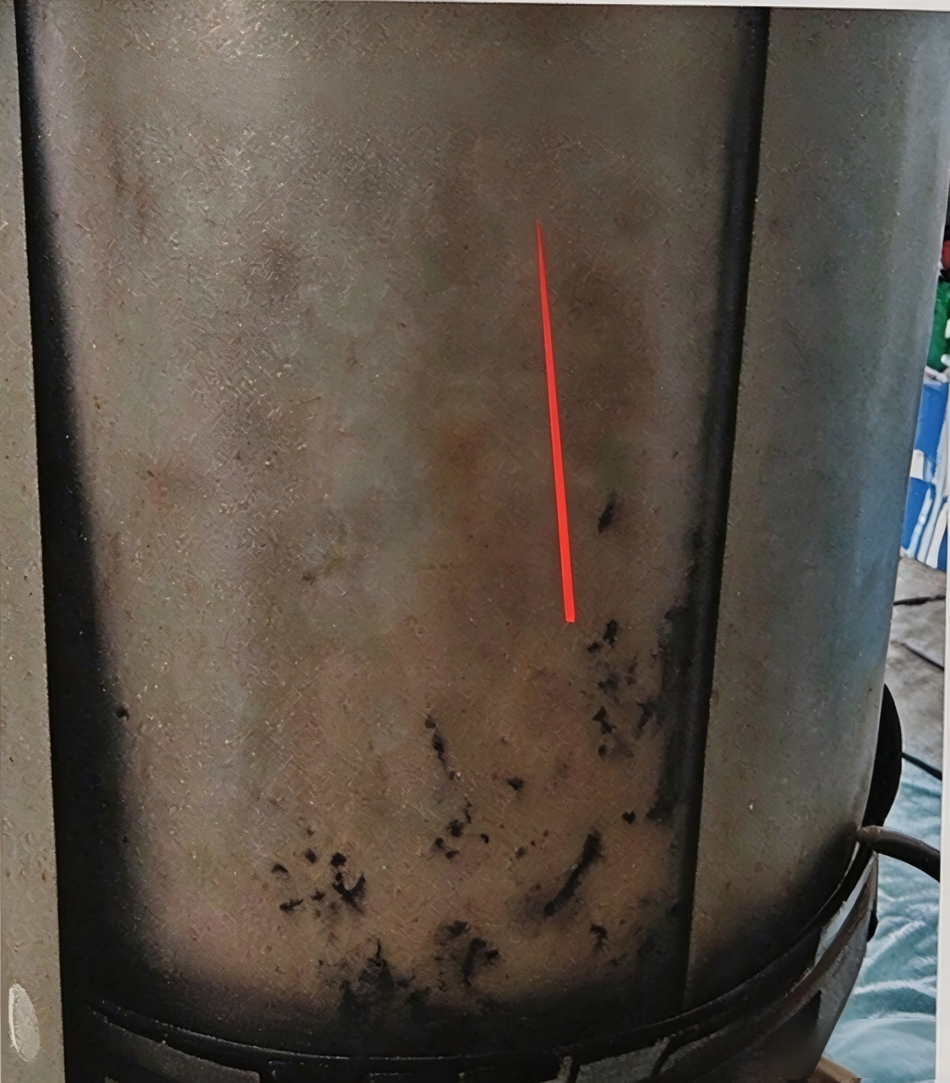
Figure 1 — Transformer core pulled out for internal inspection
3. Findings After Disassembly
After the tank cover was lifted and the core assembly pulled out, the test conclusions were fully verified on site: Phase A and Phase B windings and insulation structure were completely intact, with no burning or damage marks. Instead, damage was found on the insulating pressboard underneath the Phase‑C high‑voltage winding.

Figure 2 — Tree-like carbonized tracking marks on insulating pressboard
The board surface was covered with branching, tree‑like carbonized tracking marks. Local pressboard areas bulged due to gas produced by internal discharge. Moreover, some bulges looked intact on outer surface, but obvious black discharge burn traces could be seen after cutting open the bulged sections.

Figure 3 — Bulging insulating pressboard, comparison before and after dissection
Clear creepage tracks from surface electric current can be observed at the bottom area of Phase‑C high‑voltage winding. Outer‑layer insulation suffered the most serious carbonization and puncture damage. Damage gradually became lighter as it extended toward inner winding layers. Therefore, this evidence shows the discharge fault originated on the insulating board, and spread inward toward windings, not caused by winding breakdown itself.
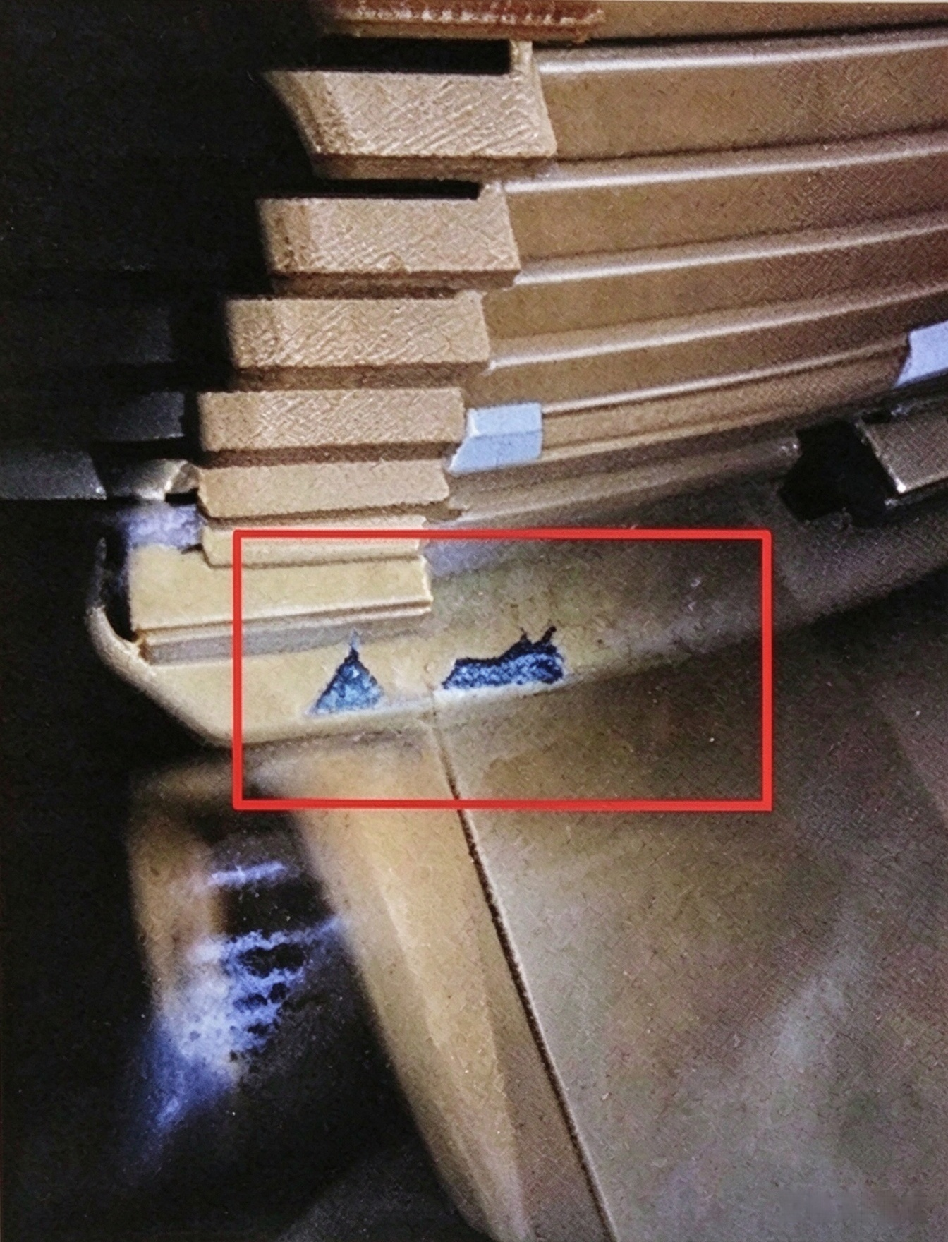
Figure 4 — Creepage and burn spots at bottom of high-voltage winding
This kind of insulation ageing risk can also occur on well‑designed amorphous core transformer products. Specifically, damage was more severe on outer‑layer insulation and gradually reduced toward inner winding layers.
4. Root‑Cause Explanation
It is critical to note: this local degradation of insulating pressboard is not an inherent manufacturing quality defect. Because over more than 10 years of continuous heavy‑load operation, the combined long‑term effects of internal electric field, oil flow and operating temperature trigger slow natural ageing of insulation materials in most power transformer units.
At the very beginning, extremely faint micro‑discharge appears at tiny weak points in the insulation. The faint discharge generates small gas bubbles, which have poorer dielectric performance than solid pressboard and break down easily. This creates a self‑accelerating vicious cycle: faint discharge → minor insulation damage → distorted local electric field → stronger discharge. Eventually, years of accumulation creates detectable sustained partial discharge.
To sum up, whether you operate dry type transformers or oil‑immersed units, long‑term monitoring remains essential.
5. Key Takeaways for All Transformer Owners
1. Routine testing of transformer oil is a critical risk‑prevention measure. Many customers treat distribution transformer hardware as maintenance‑free and skip oil sampling, since oil chromatography is the most sensitive health indicator for internal conditions. Delayed detection may turn minor partial discharge into winding burnout, bringing huge repair costs and power outage losses.
2. Stick to fixed inspection schedules. For instance, whether you deploy 75 kVA transformer, 150 kVA transformer, pole‑mounted transformer or integrated compact substation, do not wait for total equipment failure before emergency handling.
3. Proper product selection from qualified suppliers plays a vital role in extending equipment service life. When purchasing power transformers or distribution transformers, buyers should focus on product technical specifications, material standards and compliance with international testing standards. As a result, good‑quality original hardware lays the foundation for stable long‑term operation.
Conclusion
This incident was contained without large‑scale power outages, thanks to consistent routine monitoring. After all, no power transformer or distribution transformer can operate risk‑free forever. Reliable operation relies on regular inspection and early risk identification. Whether you plan to purchase new oil immersed power transformers, or you need technical support for existing equipment, please feel free to contact our team.