Two real substation incidents reveal how feeder ground faults cascade into main transformer backup trips — causing costly busbar outages and penalty clauses. This study contrasts legacy vs. patented‑optimized protection coordination for distribution transformer owners and EPC contractors.
When selecting a power transformer or distribution transformer for overseas projects, buyers face a wide capacity range: medium‑capacity 75 kVA transformer and 150 kVA transformer for local distribution, through to large 1000 kVA transformer and 2500 kVA transformer for industrial sites. Yet even well‑manufactured oil immersed transformer and dry type transformer units can suffer catastrophic cascade trips when protection coordination gaps exist on the low‑voltage side. For product references, see our oil immersed transformer product range.
1. Understanding Cascade Tripping in Distribution Transformer Protection
A cascade trip occurs when a feeder fault escalates undetected until the main transformer’s backup protection operates — instead of the feeder’s own protection clearing it first. Two fundamental fault categories determine whether differential protection operates correctly. As a distribution transformer owner or EPC contractor, understanding this boundary is critical for your protection design.
Internal‑zone faults — faults occurring within the main transformer low‑voltage protection zone. The differential protection sees opposing currents on primary and secondary windings and trips correctly.
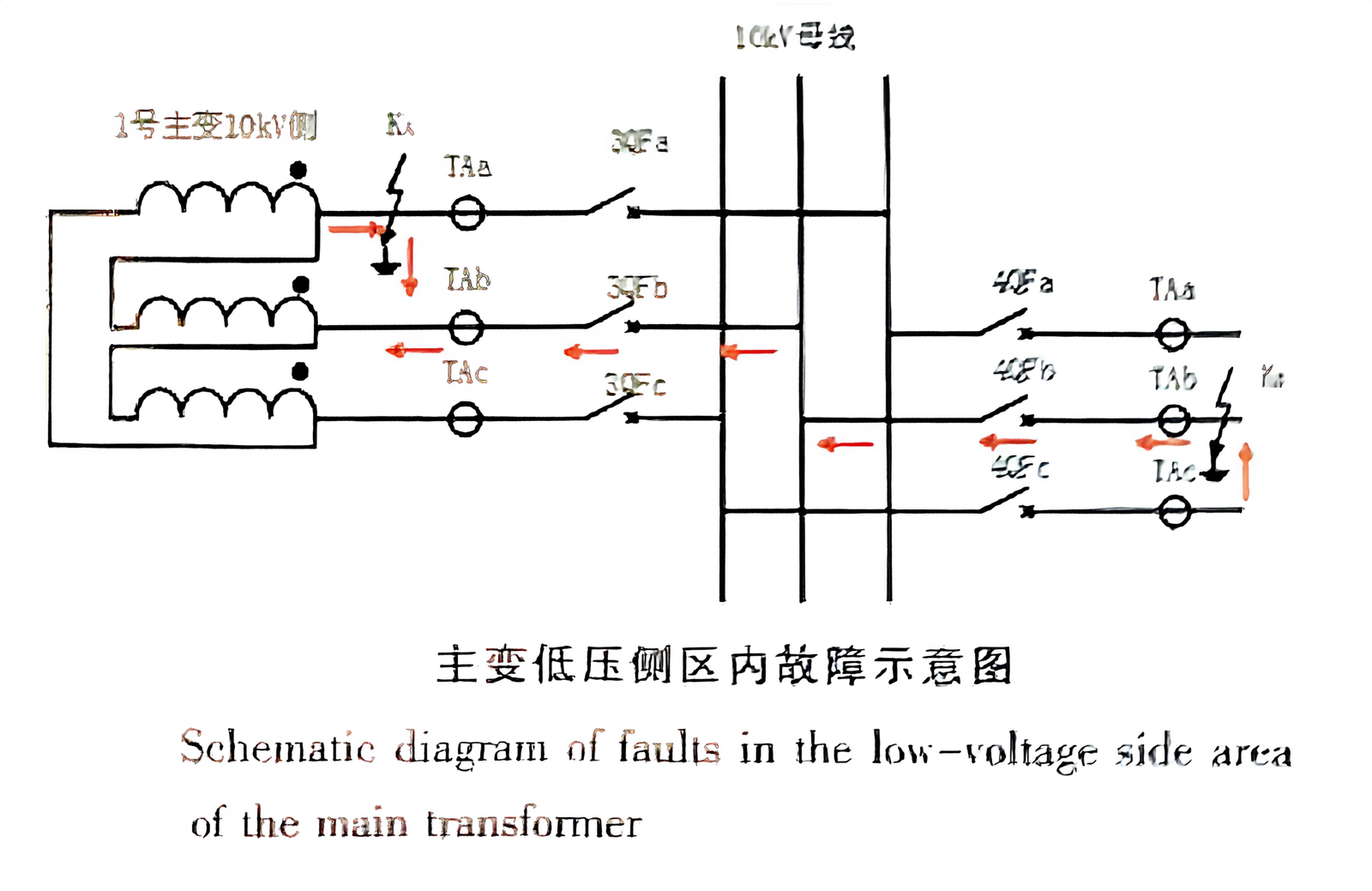
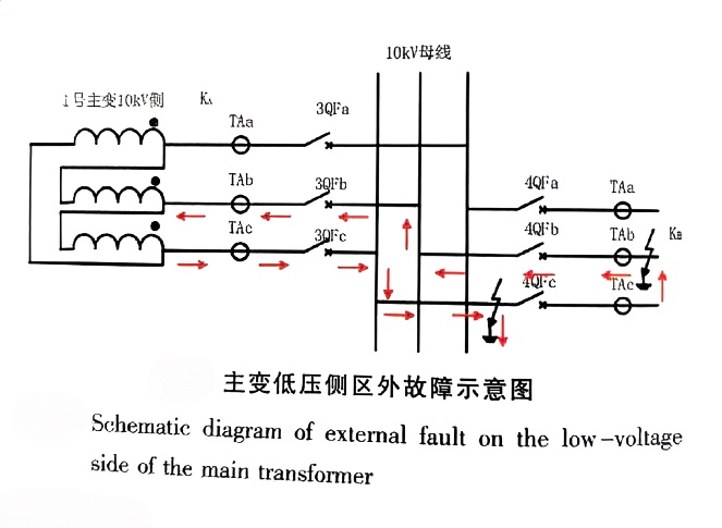
External‑zone faults — faults on feeders or busbars outside the main transformer zone. Incomplete CT phase coverage or reversed current direction can make feeder protection blind, allowing the fault to propagate inward until main transformer backup protection operates.
Industry statistics make this risk tangible: ∼50% of transformer faults involve windings or insulation, and 40–50% are linked to secondary‑side overvoltage. Short‑circuit forces can increase winding deformation stress by up to 6×.
2. Real‑World Cascade Tripping Incidents
Both cases below are documented in Transformer journal (Vol.63 No.10, 2026).
Case 1 — 220 kV Substation, 4 May 2024
This 220 kV station operated with three bus sections in parallel, two main transformers, and a 10 kV distribution bus. The single‑line diagram before the fault is shown below.
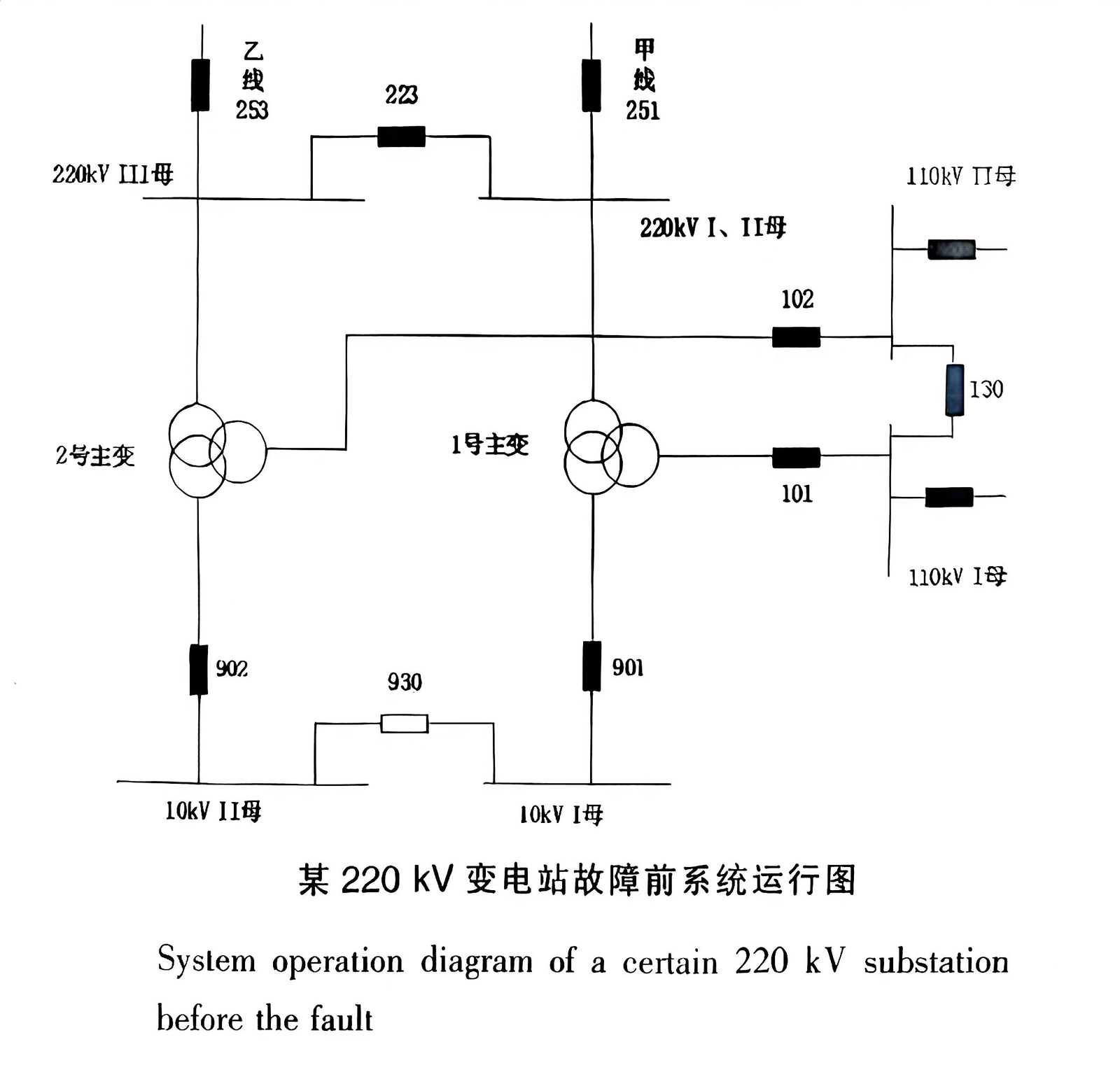
At 02:53:36, an intermittent B‑phase ground fault developed on the 10 kV Tanggang 912 feeder. The fault evolved through three stages over ∼50 ms:
- Stage 1 (0–14 ms): Classic B‑phase ground‑fault — B‑phase voltage collapsed, A and C phases rose. Feeder protection saw insufficient current and did not operate.
- Stage 2 (14–50 ms): The ground‑fault punctured the porcelain bushing at the busbar junction, evolving into a two‑phase (AB) short. Current flowed from the 220 kV side through the main transformer to the 10 kV fault point.
- Stage 3 (50+ ms): Fully developed ABC three‑phase short inside the main transformer low‑voltage zone. Main transformer #2 differential protection operated, tripping breakers 253, 223, and 902.
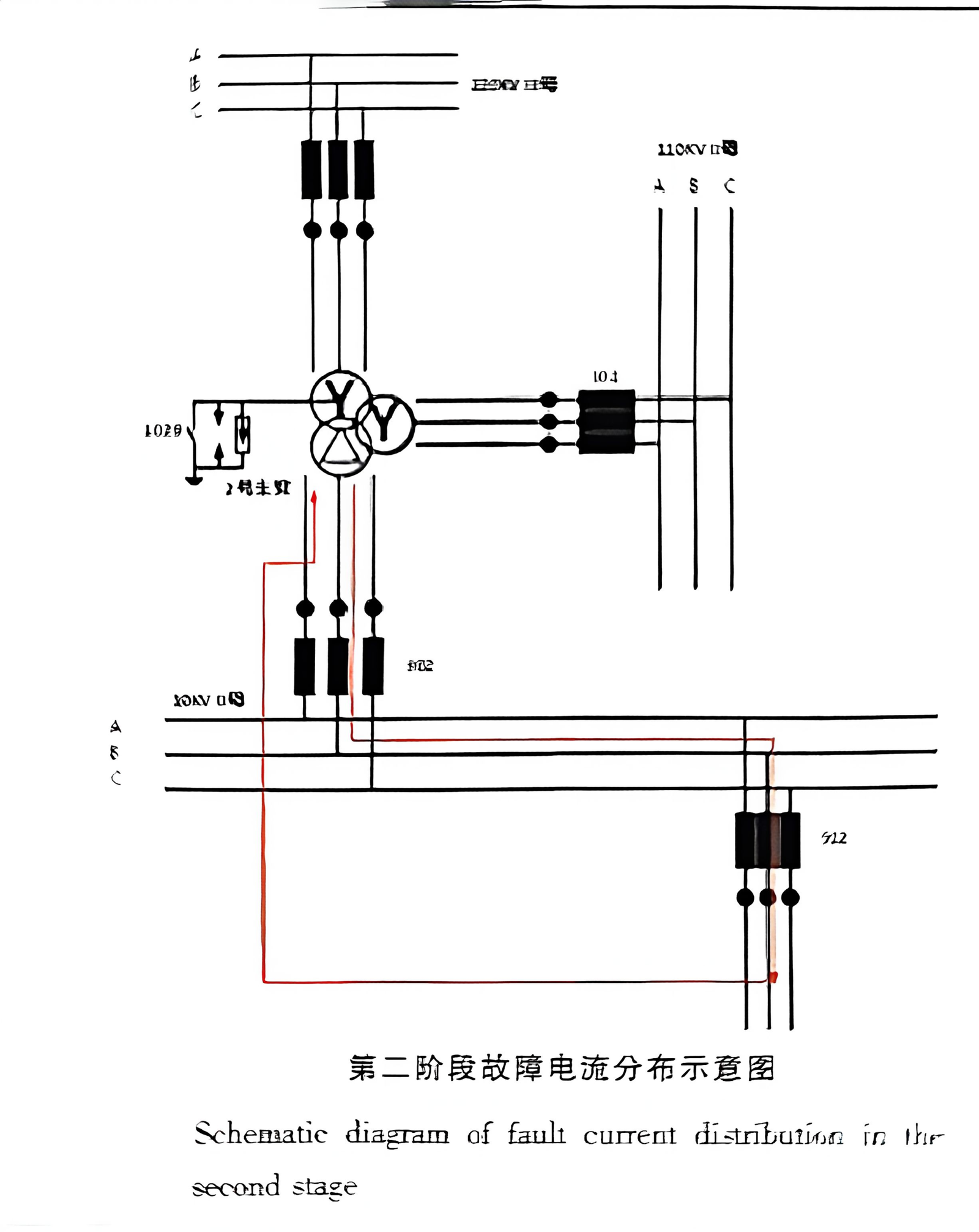
Total isolation and repair time: ∼4.5 hours. The root cause: feeder protection configuration never reached the pickup threshold for the evolving fault, allowing it to escalate into an internal zone event that the main transformer’s differential protection finally cleared.
Case 2 — 110 kV Substation Distribution Transformer, 18 May 2024
This station used a 110 kV ring bus with two main transformers feeding separate 10 kV bus sections. The layout is shown below.
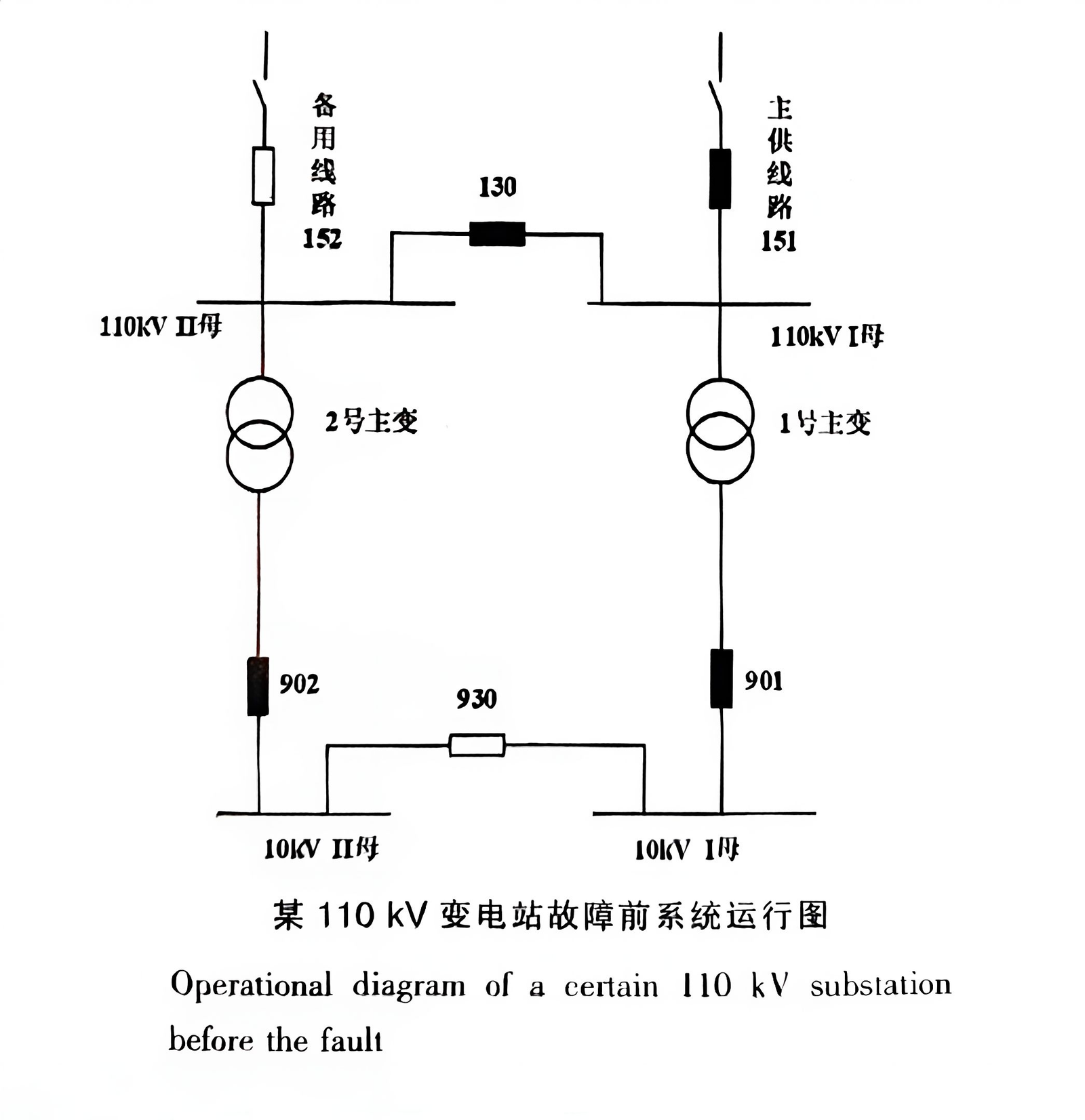
At 23:13:24, a heteronymous two‑point ground fault developed — K1 grounded on bus M A‑phase, K2 grounded at distance l₂ from M on C‑phase — on separate 10 kV feeders. The main transformer low‑voltage backup protection tripped after 49.8 ms, cutting power to 12 downstream end‑users — a typical financial penalty scenario for distribution transformer operators.
3. Patented‑Optimized Distribution Transformer Solution
For EPC projects requiring enhanced cascade‑trip resistance, we supply optimized oil immersed distribution transformer and dry type distribution transformer units incorporating patented utility‑model structures. The following comparison uses field statistics and IEC 60076 test methods.
Core Patented Structures
- Auto oil‑filling & sealing patent — maintains transformer oil cleanliness, reinforcing low‑voltage insulation against feeder‑fault overvoltage
- Winding‑restraint short‑circuit‑resistant patent — controlled‑tension winding suppresses coil displacement under high fault current
- Vibration & noise reduction patent — multi‑stage spring‑damping sound‑absorbing structure targets 8–12 dB(A) reduction per IEC 60076‑10
- Quick‑mount & rotatable terminal‑plate patent — adapts to non‑standard mounting supports, reducing on‑site wiring time
4. Key Takeaways for Distribution Transformer Owners & EPC Contractors
- Complete CT phase coverage is non‑negotiable. As Case 2 demonstrates, missing even one phase on feeder CT blinds protection to heteronymous two‑point ground faults. Run a full CT coverage audit on every 10 kV feeder in your compact substation or distribution system.
- Minimize external‑zone fault exposure. The boundary between internal and external faults directly determines whether differential protection operates correctly. Review IEEE 242 buffering considerations.
- Optimized impedance and restraint structures matter. Patent‑optimized designs reduce fault‑current amplification and winding displacement — addressing both the cause (fault escalation) and the symptom (hardware damage).
- Long‑term monitoring remains essential. Whether you operate a dry type transformer or an oil‑immersed unit, consistent transformer maintenance including IEEE 10257160 short‑circuit analysis catches issues before they trigger cascade failures.